

Overview#
This article describes the steps to allow inbound access from trusted WAN-side devices, to services running on the LAN side of the OPNsense firewall.
This process involves making changes to the WAN interface configuration, setting static routes on the edge router (ISP/home router), and using aliases for easy grouping of common ports, Proxmox hosts and trusted devices.
Example Scenario#
The OPNsense firewall for my lab environment sits behind my ISP router in the home network. I have two host servers running Proxmox VE on the LAN side of the OPNsense firewall.
The goal is to access the web interfaces for the Proxmox hosts and my network switch from my laptop connected to the home network.
Internet
    |
ISP Router (HOME NETWORK: 172.16.0.254/24)
- Laptop [172.16.0.10]
    |
OPNsense WAN: 172.16.0.250
    |
OPNsense LAN: 10.0.0.0/24
- Proxmox Node 1 [10.0.0.10]:8006
- Proxmox Node 2 [10.0.0.11]:8006
- Switch [10.0.0.250]:80Aliases#
Aliases can make configuring the firewall easier, as it allows the grouping IP addresses or ports, enabling firewall rules to be assigned using the groups rather than specifying individual rules for each source and destination.
Using aliases is not required, however it does make management much easier. Individual IP addresses can be used instead if preferred.
Create the alias groups for trusted WAN devices, Proxmox nodes, network devices and management ports.
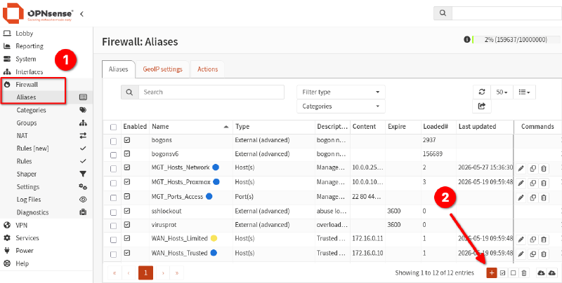
- Navigate to
Firewall > Aliases. - Click the
+button to create a new entry. - Enter a name fo the alias group.
- Select the alias Type as
host(s). - Add the IP addresses of the Proxmox hosts.
- Click
Save, followed byApply. - Repeat the process for WAN tusted devices and management ports (selecting type = ports).
Trusted WAN Hosts:
- Laptop (172.16.0.10)
Name: WAN_Hosts_Trusted
Type: Host(s)
Content: 172.16.0.10
Description: Trusted device access to management via WAN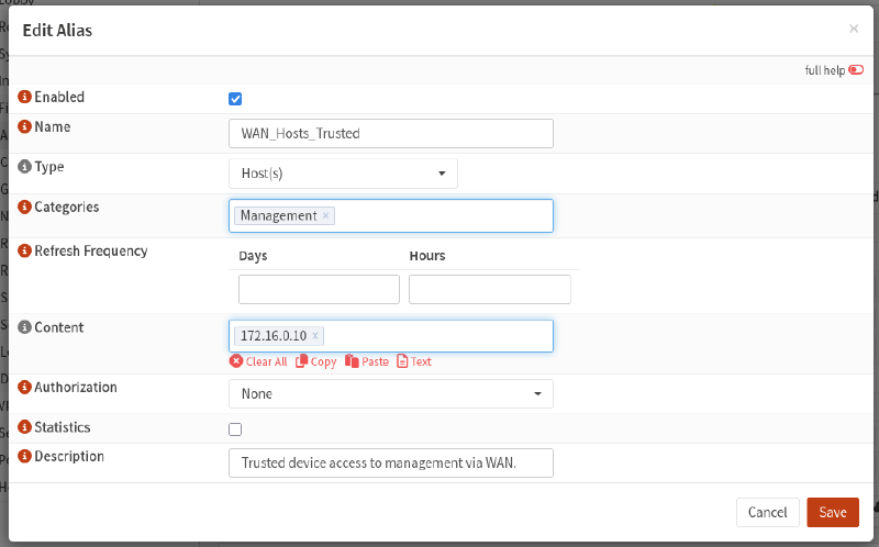
Proxmox Hosts:
- Node 1 (10.0.0.10)
- Node 2 (10.0.0.11)
Name: MGT_Hosts_Proxmox
Type: Host(s)
Content: 10.0.0.10, 10.0.0.11
Description: Management - Proxmox Nodes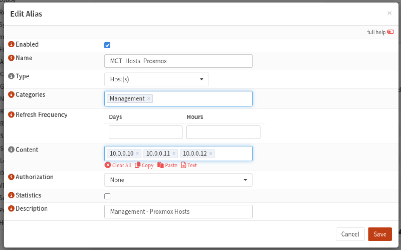
Network Hosts:
- Switch (10.0.0.250)
- OPNsense LAN address (10.0.0.254)
Name: MGT_Hosts_Network
Type: Host(s)
Content: 10.0.0.250, 10.0.0.254
Description: Management - Network Devices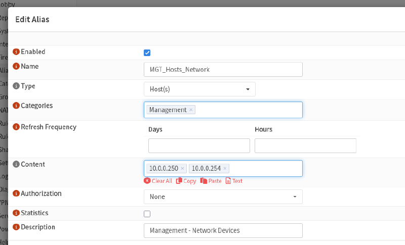
Management Ports:
| Port | Protocol | Description |
|---|---|---|
| 22 | SSH | Remote shell access |
| 80 | HTTP | Web interface access |
| 443 | HTTPS | Web interface (secure) |
| 8006 | Proxmox | Proxmox web interface |
Name: MGT_Ports_Access
Type: Port(s)
Content: 22, 80, 443, 8006
Description: Management - Port Access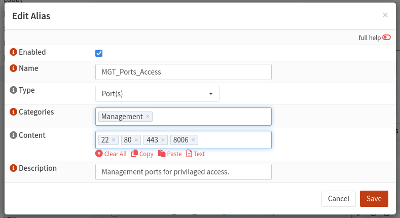
ISP Router Static Routes#
With OPNsense located behind the existing home network, as per the example earlier, we need to tell the home ISP router where to send traffic destined for the Proxmox nodes.
This method uses an entry in the route table of the ISP router to direct traffic matching the network address of the Proxmox hosts via the WAN address of the OPNsense firewall.
- Login to the ISP router web interface and locate the setting for
Static Routes. - Create an entry directing the target address space (LAN behind OPNsense) to the OPNsense WAN IP address used in the ISP router network.
Destination Range: 10.0.0.0/16 --> OPNsense WAN Gateway: 172.16.0.250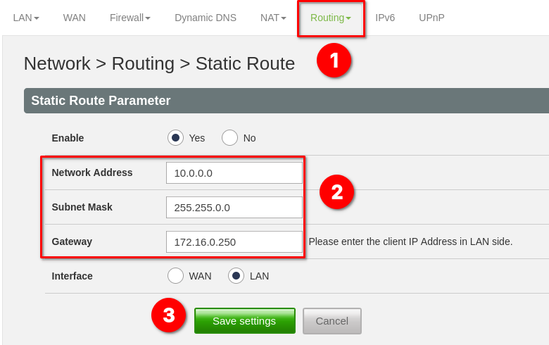
Example:
Internet
    |
ISP Router (HOME NETWORK: 172.16.0.254/24)
- Laptop [172.16.0.10] --> 10.0.0.10:8006
Static route: 10.0.0.0/16 --> 172.16.0.250 (OPNsense WAN address)
    |
OPNsense WAN: 172.16.0.250
    |
OPNsense LAN: 10.0.0.0/24
- Proxmox Node 1 [10.0.0.10]:8006
- Proxmox Node 2 [10.0.0.11]:8006
- Switch [10.0.0.250]:80
Disable Outbound NAT#
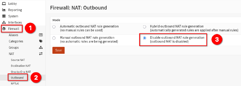
For this method, we need to disable outbound NAT. The upstream ISP router is capable of routing and NATing traffic from the downstream networks, which removes the need for OPNsense to perform outbound NAT, and prevents double NAT between internal networks.
- From within the OPNsense web management interface, select
Firewall > NAT > Outbound. - Select the setting
Disable outbound NAT rule generationand clickSave.
Confirm Reply-To on WAN Rules#
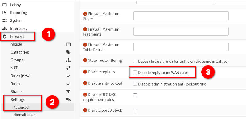
The next step is to ensure Disable reply-to on WAN rules is unchecked.
OPNsense automatically applies reply-to to WAN rules.
This associates a return gateway with traffic entering through the WAN interface and helps ensure that response traffic follows the expected path for the firewall state.
In this environment, OPNsense sits behind an upstream ISP router and uses static routing (10.0.0.0/16 –> 172.16.0.250) to provide access to lab networks.
Keeping reply-to enabled allows state tracking and return traffic handling to function correctly when accessing devices such as Proxmox hosts from the upstream home network.
During testing, disabling reply-to caused connectivity issues to routed LAN hosts in this environment.
For OPNsense management, I will use the LAN interface address rather than the WAN interface address. In this design, the WAN interface primarily acts as a transit interface to upstream networks rather than a dedicated management interface.
- Naviagte to
Firewall > Settings > Advanced. - Locate and ensure the option
Disable reply-to on WAN rulesis unchecked.
Firewall Rules#
We need to create rules to allow the traffic to pass inbound via the WAN interface to the devices behind the LAN interface.
- Navigate to
Firewall > Rules. - Click the
+button to create new rules. - Configure the new rules using the aliases created previously.
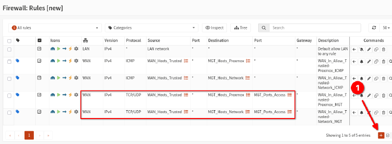
Example: Inbound on WAN, allow Trusted to access Proxmox on management ports.
Interface: WAN
Action: PASS
Direction In
TCP/IP Version: IPv4
Protocol: TCP/UDP
Source: WAN_Hosts_Trusted
Source Port: Any
Destination: MGT_Hosts_Proxmox
Destination Port: MGT_Ports_Access
Log: Enabled
Description: WAN_In_Allow_Trusted-Proxmox_MGT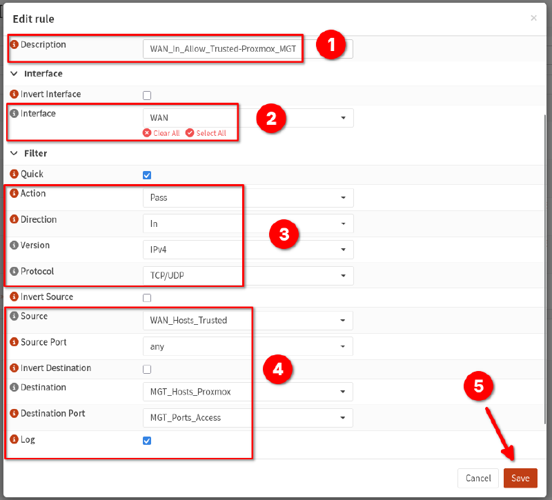
- Repeat the rule addition process for the remaining aliases where required.
Validation & Testing#
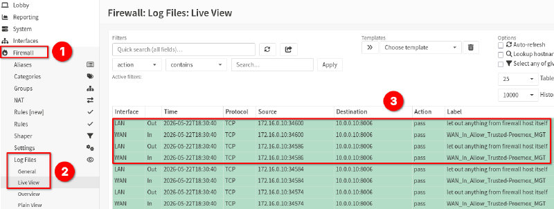
This should now allow the WAN devices with IP addresses listed in the WAN_Hosts_Trusted alias to connect to the Proxmox hosts listed in the MGT_Hosts_Proxmox alias group.
If logging is enabled for the rules, these requests should be visible in the OPNsense firewall logs.
Cover photo by U. Storsberg on Unsplash with OPNsense logo overlay.